Polymorph Selection
One of the most fascinating problems in crystallisation is the generation of different crystal polymorphs. Many industrial products require the production of specific polymorphs, where these often exhibit unique morphologies, sizes and stabilities, and these may not be readily formed during conventional synthesis or found in mineral reserves.
We have attempted to provide a predictive understanding of why unstable polymorphs are formed or how to selectively form particular polymorphs. This has involved understanding of both the thermodynamics and kinetics of nucleation and growth and use of a combined theoretical and experimental approach to explore how different reaction conditions drive the formation of different polymorphs.
In order to study crystallisation processes experimentally we have successfully developed and benchmarked a correlated microscopy approach to study crystallisation and phase transformation at the micro/nanoscale in-situ and in real time. We have employed in-situ liquid cells for both the transmission electron microscope (TEM), the scanning electron microscope (SEM), the Raman optical microscopy and the hard X-ray (I14) beamline at Diamond. We have also extensively investigated time-resolved cryogenic TEM and have also extensively investigated different sample preparation methods for conventional “dry sample” TEM. Each method suffers from its own drawbacks and artefacts including radiolytic damage by the electron/X-ray beam, sample confinement and sample preparation artefacts, however a correlated approach which can be benchmarked against cryo-TEM appears to be the best way forward. Reference: Ilett M. et al “Analysis of complex, beam-sensitive materials by transmission electron microscopy and associated techniques”, Phil. Trans. R. Soc. A (2020) 378, 20190601.
Calcium Sulfate
In terms of the crystallisation of calcium sulfate, some literature studies have suggested that the crystallisation of gypsum (calcium sulfate dihydrate) proceeds in a two step process via a bassanite (calcium sulfate hemihydrate) intermediate. We studied the transformation of bassanite to gypsum using our correlated microscopy approach and showed that the predominant pathway was dissolution of bassanite followed by precipitation of gypsum rather than oriented attachment of bassanite nanoneedles followed by a solid state transformation. Reference: Ilett M. et al “Evaluation of Correlated Studies Using Liquid Cell- and Cryo-Transmission Electron Microscopy: Hydration of Calcium Sulphate and the Phase Transformation Pathways of Bassanite to Gypsum”, J. Microscopy (2022) 288(3), 155-168.

Figure 1: Published study on the hydration of bassanite to gypsum using a correlated microscopy approach.
We have also studied to the direct crystallization of gypsum from solution using TEM and a range of different sample preparation methods. Observation of bassanite appears to be a sample artefact of drying or chemical quenching, whilst Cryo-TEM indicates that gypsum forms from bulk solution via a classical nucleation route.
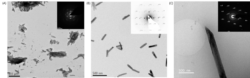
Figure 2: TEM images taken after 30 min of mixing equimolar 50 mM CaCl2 and Na2SO4 prepared via (A) vacuum drying (B) ethanol quenching and (C) Cryo-TEM. Bassanite is favoured when prepared either through drying or ethanol quenching, yet cryo-TEM preparation does not indicate any bassanite at this time point.
We have developed a new and general theoretical method for calculating interfacial free energies. The method has been refined to reduce the number of calculations required and avoid potential discontinuity in the thermodynamic integration. We have applied our method to the CaSO4.xH2O system and calculated their interfacial free energies of both bassanite and gypsum with pure water. The calculated interfacial free energies were used in a Wulff construction to predict the equilibrium morphology of bassanite and gypsum which closely resemble the experimentally found morphologies. We also predicted the relative stabilities of bassanite/gypsum nanoparticles as a function of CaSO4 formula units which showed at observable sizes, a bassanite nanoparticle is never more stable than a gypsum nanoparticle. However, the interfacial free energies of bassanite have a greater entropic contribution and so may be more susceptible to changes in conditions. Once a bassanite nanoparticle has formed, it’s growth may then be controlled kinetically due to the difficulty of hydrating the bulk structure into gypsum. Reference: Yeandel S., Freeman, C.L. and Harding, J.H. “A general method for calculating solid/liquid interfacial free energies from atomistic simulations: application to CaSO4.xH2O”, J. Chem. Phys. (2022) 157, 084117.
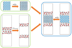
Figure 3: Schematic of the method for calculating interfacial free energies
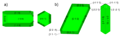
Figure 4: Predicted equilibrium morphologies of a) bassanite and b) gypsum.
Calcium Carbonate
In collaboration with Industry, we have studied the industrially relevant transformation of calcium hydroxide to calcium carbonate via carbonation using in-situ liquid cell TEM. Dissolution of hydroxide single crystals led to the evolution of intriguing, partially-filled hexagonal structures that can be attributed to the pseudomorphic precipitation of amorphous calcium carbonate (ACC) which then dissolves and re-precipitates as scalenohedral calcite.
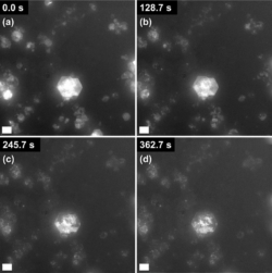
Figure 5: The dissolution of hexagonal Ca(OH)2 observed using LCTEM. Scale bars are 1 µm.
We have also investigated the early stages of crystallisation of calcium carbonate from bulk solutions at varying levels of supersaturation. As for the case of the calcium sulfate system, different sample preparation methods were observed to give slightly different results, hence care is required [Ilett et al. Journal Microscopy in press]. Cryo-TEM suggested that the process proceeds via a multi-stage pathway involving the initial formation of dense liquid phase, followed by precipitation of ACC followed by transformation into crystalline polymorphs – calcite and vaterite for the case of equimolar precursor concentration ratios and aragonite for the case of very carbonate rich conditions. This emergent aragonite appears to involve self- assembly of small nanometre-sized hydrated ACC units into chains which then form a fibrous structure. This morphology is common to aragonite produced in the presence of high levels of magnesium, in alcohol containing solvents and also in confined graphene pockets suggesting a common mechanism.
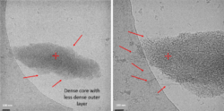
Figure 6: Cryo-TEM images of emergent aragonite structure after 20 min showing Fibrous nanowire structures.
Theoretically, using the new method developed for calcium sulfate, we have calculated the interfacial energies of various calcite and aragonite surfaces in contact with water. Our work has resolved the inconsistencies in surface energies that suggested aragonite should be more stable. The calcite {104} surface is the most stable, it is significantly lower in energy than any other calcite surface and lower than all the aragonite surfaces. The aragonite surfaces have a much greater variety in calculated energies, in agreement with the more complex morphologies observed experimentally. The Wulff construction was used to predict the crystal morphologies of hydrated calcite and aragonite from the interfacial free energies and shows good agreement with the experimental morphologies. For all calcite surfaces, the entropic contribution is much lower than the enthalpic contribution. For the aragonite surfaces the contributions are more varied than for calcite, but in all cases the entropy contribution is far more significant than for the calcite {104} surface. Not only does this highlight the importance of including entropy in the interfacial energy calculation, it could also be key in understanding the selection of the aragonite polymorph over calcite.
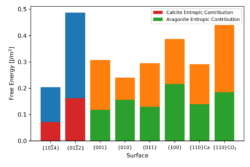
Figure 7: Variation in surface free energy for calcite and aragonite (enthalpy and entropy contributions are denoted by blue/red for calcite and gold/green for aragonite) at 300 K.
We have also developed new simulation tools to identify any potential pre-disposition of the ions to particular phases prior to nucleation. Applying our tools to the calcium carbonate system has shown that ion coordinations indictativve of the aragonite phase form far less than those of calcite. This indicates a potential kinetic difference between the two phases that also helps drive the formation of calcite. We have examined other solution conditions to see if this balance can be shifted in relation to experimental conditions that favour aragonite formation.